I no longer update this blog, please search for information on youtube 'paul crisp roadster'
This blog is about the conversion of a Smart Roadster to be a fully electric plug in car
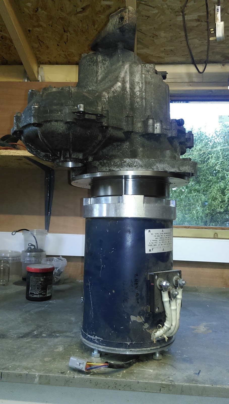
Finally got the motor connected to the gearbox and lifted it into the frame. I thought I would be pre-making the mounts but instead I offered the motor into place attached to the gearbox and hanging from a hoist, then using the gearbox mount bracket to set the position I measured and cut the other 2 mounts from an old scrap metal stand.
Curtis controller just tacked on to get the wires connected ready for a first run.
Here are some more photos of it in place
The lifting eye was balancing it quite well although the motor end was slightly heavier.
LH and front mount plates made from 3mm scrap sheet metal, it was already folded along some edges so I cut the shape I needed from it and didn't need to fold any parts
Offered the drive shafts up, had to unbolt the top of the shock absorbers to allow the arm to drop far enough to get the wheel end of the drive shafts in
Would of been almost impossible without the hoist as I could hardly lift the motor and gearbox together. Although new the hoist was surprisingly cheap from ebay.
Managed to find some time to get started on the motor mounting parts. A bit of a change of plan on ways to mount the motor to the gearbox, instead fo making a bespoke part from scratch I found that I could base the adapter on a standard disk brake as it was already the same shape. After looking around a bit I found a Suzuki Jimmy SUV front disk brake was the best fit, it has a 289mm OD and is 41mm deep, ideally it would have a 101.8 hole but it was 107 so I need to make a centering ring, but it's pretty close. I'm hoping the fact disk brakes are Iron/carbon is not going to be a problem, apart from being a bit heavy.
I've drilled it out to fit the gearbox, as I only have access to a mill without a readout the easiest way was to reference everything from a corner, this drawing shows the hole positions.
So I now have the mount plate made, and all the holes seem to line up quite well. Turned a couple of locators to help with final alignment onto the gearbox
Also turned the shaft to spline adapter, although I've simplified it a bit when I turned it as I wasn't able to do the rotated arcs on the manual mill, but the parts seem to fit together well.
So I've offered up the gearbox onto the motor with the parts and it looks ok, the thinner than originally planned disk based adapter does mean the end of the spline hits on the end of the motor shaft by 2mm but I'll cut off the end of the spline. Having the motor closer to the gearbox will be a big benefit to fitting the whole lot into the frame as there is very little space between the motor and frame.
Work on the conversion has been on hold for a couple of months now, with young children and work there's just not enough time left over to spend on this at all. Hopefully I can get back into doing some work on it again soon and finish off the mounts and drive connector. Once that's done then it's only a quick wiring up job to have it working on the stand.
Now everything is painted and cleaned it's ready to go together.
I don't yet have the motor mounting plate or shaft adapter but the frame can go together and I'll find out how much space there really is for the motor.
This is the lower arm assembly, just the hinging arm sitting on the coils.
I decided to make up a timber stand to hold the upper frame off the floor. This has made things a lot easier to work on. So now the gearbox is in place held by just one mount on the left hand side, the drive shafts aren't in properly yet as I've just remembered that I need to buy new oil seals so the drive shafts are just hanging in place for now. With the motor spaced as intended with the proposed mount plate it really does only just fit, this is purely a stroke of luck as it didn't occur to me that the motor was going to be longer than the original engine, fortunately the CAD model came out just about right which is useful to know.
So now I know it's all fitting I need to make up the motor-spline connection and wait for the motor mount to be machined. I've ordered the seals, didn't seem any point in ordering smart ones so I've ordered standard 40ID x 60OD x 10 wide R23 seals which are identical but only £3 each.
Now I can work out how to mount the motor to the two engine mount points, looking forward to wiring the motor now for the first test run.
One of the early things I checked on was is a 450 frame suitable to use for a roadster.. and it was apart from two things;
The handbrake cable points forwards to connect the the handbrake in the Roadster whereas it points up on a fortwo.
The Roadster doesn't use the anti-roll bar that normally comes with the fortwo frame.
So the anti-roll bar job was very easy and just involved cutting off the brackets..
The handbrake cable mod meant cutting off the old bracket and making a new one that points forwards, I knew what it should look like from my exiting Roadster so I managed to make a new bracket from the old bracket with a bit of cutting and folding and then welded it on. Susequently I have for the handbrake cables seem a bit short but if I don't clip it to the normal clip points then it works fine.
Having all the parts cleaned an painted seemed like a good opportunity to measure them up and model them in CAD. So now all the major parts are drawn and it looks like the motor is only just going to fit, it did come with a back plate to create a ventilation space and also protect the encoder on the back of the motor. However there is definitely no space for that so I've assumed it can't be fitted.
This view shows the motor and motor mount sectioned and the motor shaft mount and clutch spline.
I've bought a taperlock bush and flange plate to lock onto the motor shaft. The taper lock is a 1610 size with a 1 1/8" bore, the plate is a BF16 plate which is 120mm diameter with 6 x 8mm mounting holes at 110mm PCD.
Instead of buying a whole Smart clutch plate which normally comes as a complete assembly I've found that a Ford fiesta MK1 1.0 clutch plate fits the 19mm 17 spline shaft perfectly, just a few £s from ebay. So the plan is to cut off the clutch friction plate and use the inner plate and probably keep the springs as they will act as a bit of a shock absorber which might be useful.
I've had a go at controlling the gear selection motor and it seems to broadly work now. I've done a quick video to explain.
This is a better video with the voltage now running at 12v, motor takes around 5A on a move and has a bit of a kick to it.
I've had some requests for the Arduino code I used, this was based on some stuff I found on the web, (sorry but i can't remember the source) and my rather limited abilities with Arduino. I then connected this to Makerplot which is a serial port plotter capable of sending and reading some simple commands. It works in a rather odd way as the GUI is a macro you load up, but it's a great program once you're used to it.
So the Arduino code is shown below..
This is a link to the Makerplot software - http://www.makerplot.com/
and the is the macro for the Makerplot as shown on the vid.
This is the photo I found which shows the connection onto the Smart gear selection motor
also a handy schematic of the pins and encoders
----------------------------------- Code to drive motor as shown in the youtube video ------------------
please note, this is note code written spacifically for this project so there is some stuff in here which is not really needed... but it worked for me. You'll probably need to tweak around with the PID settings.
/*
This program uses an Arduino for a closed-loop control of a DC-motor.
Motor motion is detected by a quadrature encoder.
Two inputs named STEP and DIR allow changing the target position.
Serial port prints current position and target position every second.
Serial input can be used to feed a new location for the servo (no CR LF).
Pins used:
Digital inputs 2 & 8 are connected to the two encoder signals (AB).
Digital input 3 is the STEP input.
Analog input 0 is the DIR input.
Digital outputs 5 & 6 control the PWM outputs for the motor (I am using half L298 here).
Please note PID gains kp, ki, kd need to be tuned to each different setup.
*/
#include <SPI.h>
#include <PID_v1.h>
#define encoder0PinA 2 // PD2;
#define encoder0PinB 8 // PB0;
#define IS_1 0
#define IS_2 1
#define IN_1 3
#define IN_2 11
#define INH_1 12
#define INH_2 13
volatile long encoder0Pos = 0;
long previousMillis = 0; // will store last time LED was updated
long target1=0; // destination location at any moment
int countStep;
//for motor control ramps 1.4
bool newStep = false;
bool oldStep = false;
bool dir = false;
void loop(){
input = encoder0Pos;
setpoint=target1;
myPID.Compute();
pwmOut(output);
// print encoder and target every second throgh the serial port
if(millis() > previousMillis+200 ) {Serial.print(encoder0Pos); Serial.print(","); Serial.println(target1); previousMillis=millis(); //}
// interpret received data as an integer (no CR LR)
void doEncoderMotor0(){
if (((PIND&B0000100)>>2) == HIGH) { // found a low-to-high on channel A; if(digitalRead(encoderPinA)==HIGH){.... read PB0
if ((PINB&B0000001) == LOW) { // check channel B to see which way; if(digitalRead(encoderPinB)==LOW){.... read PB0
encoder0Pos-- ; // CCW
}
else {
encoder0Pos++ ; // CW
}
}
else // found a high-to-low on channel A
{
if ((PINB&B0000001) == LOW) { // check channel B to see which way; if(digitalRead(encoderPinB)==LOW){.... read PB0
// encoder is turning
encoder0Pos++ ; // CW
}
else {
encoder0Pos-- ; // CCW
}
}
}
I've been looking at how to connect the motor and gearbox so that I can get the adapter plate made ready to bolt it all in to the frame soon.
I've modeled the gearbox, motor, curtis controller and gearbox mount so far, I'll model the rest of the frame and main parts just to get an idea of how it fits together as it seem like a good opportunity to draw it up and when I was looking into doing this I couldn't find any information or dimensions for any of the Smart components. The gearbox is representative and the casting shape not accurate, although the holes and shafts positions should be close enough to make sure things line up.
This is the mount plate, Dia 290mm and 70mm thick, this thickness is needed to move the motor far enough away to prevent the motor shaft and gearbox spline clashing. I'm hoping to track down a clutch spline cheaply but the Smart clutch is a whole assembly which I don't need. The cutout is for the drive shaft, so the motor couldn't be much larger diameter.
Section of the mating parts, just need to sort out a coupling but I think this will be a taper lock plate bolted to a clutch spline, some compliant connector would be good to prevent excess wear on the bearings.
Seems like a good time to get a layout of the system drawn up to make sure I'm covering everything.
This schematic shows the layout of the main parts and how they interconnect, it breaks down the physical areas of the car and shows what will go where.
Blue boxes are things that already exist in the car and the Green boxes show components that will need to be added.
As I haven't touched the car yet I'm sure some other things will present themselves but it seems a good place to start.
The Curtis controller has a 'typical' wiring layout...
The datasheet is here http://curtisinstruments.com/index.cfm?fuseaction=Products.home#/motorcontrollers/64
I've also stumbled across this one page wiring system in a forum, this was marked as 'free to share'. Not exactly as I intend to use but a useful reference that makes some sense of the curtis diagram, for example the Pot2 appears to be used on the Brake peddle to provide regen during braking.
So these are the parts I have so far for the drive.
HPEVS AC35 motor
Curtis 1238 6501 controller - 80v 550A
A load of good quality pre-terminated cables
Curtis throttle pot with switch
Chunky solenoid
2 used chunky fuses
Curtis 840 battery gauge
The 35 way Curtis cable connector pre-wired
Coupled to this will be a standard Smart 450 gearbox/transmission. I got this from ebay, unfortunately the person used another photo from someone else's listing so the one I thought I was getting looked in better condition, but this one should do the job. More on this to follow next..
This is sort of where it starts, the subframe is built completely independently of the rest of the car and contains all you need to make a self contained driven unit. It's fairly easy to remove from the car so it's the easiest way to swap out the current petrol engine (ICE). Ideal for this kind of project. It turns out the Smart fortwo 450 has the same subframe as the Roadster 452 apart from the 450 has an anti roll bar and a slightly different hand break cable position, but the 450s are much more readily available so easy to find, I've bought this one from someone from the Smartz forum, it's in good condition and after a quick jet wash it's ready for a qui
ck sand and a coat of paint.
This is the car I'm going to convert, it's a 2004 Smart Roadster Coupe.
It's a great fun car to drive but is renowned for having an interesting gearbox, although in many ways ahead of it's time, but due to the motor controlled clutch and gear selector being fairly new it is slow off the start and the semi-automatic gear change causes the car to be a bit unpredictable with few people driving it in full automatic mode... although semi auto helps you are never quite in control of the clutch. However, the car looks great, and the feeling of being wrapped in the confined cockpit makes you feel a part of the experience. The petrol engine has a great power to cc ratio providing up to 80BHP from a 698cc engine (100BHP with the Brabus), scaled up that's better than most modern cars.
What would it be like as an electric car... perhaps with the light weigh and small space this is what it always should have been. I guess I'll find out.
But enough of the car, I won't be doing anything to it for a while as the intention is to get the running subframe finished first.
I don't intend on dismantling the Roadster and then starting the conversion. Instead, as Smarts have a subframe with the rear suspension, gearbox and engine all mounted on it which is then bolted up under the car it makes sense to buy a set of subframe parts and build a fully working electric drive version, once it's all finished and running this can then be easily swapped with the petrol version so it should then only require minimal effort to finish it.
I'll be using a full AC motor system as they have a wider rev range, regenerative braking and are more efficient than a simple DC motor. The cost will be higher but the effort will be more or less the same so it would seem to be the better option.
Normally you wouldn't need a gearbox with an AC electric motor, they have a wide torque range and are high revving but the one I plan on using with a controller with a 80v limit means I'll probably need to be able to change gear ratios so that I have some acceleration at lower speed and it won't rev out at the top end.
I've always been interested in electric cars, ever since being involved in the Battery Vehicle Society in the 80's racing home made electric cars around various kart and bike tracks for hours, seeing who could go the furthest on 2 car batteries.
Many years have passed since then but more recently I leased a Nissan Leaf through my companies green car scheme for 2 years. Leaf's aren't exactly the best looking cars and living with a car with a range of 70 miles can be frustrating, but the feeling of driving something now which we will all be driving in the future was great. The pull from a standing start, continuous acceleration and lack of maintenance is great, unfortunately some EV's are slow or people drive them slowly, but they don't need to be. I also got to drive a Tesla Model S, without doubt the best car I've ever driven in every way, but unfortunately at cost few can afford.
I bought the Smart Roadster 4 years ago, I love the looks and the fun handling but ever since owning it I've though this car should be electric. So after a lot of thought, a lot of searching for parts and too much time seeing what other people have done, it's time to make a proper start on planning the conversion.
Finding good information on conversions that have been done so far is quite difficult, so I figure I should try and document it properly in case anyone else might be interested. I've never blogged before but I'm assuming this will be the best way to do it.. time will tell. I hope you find it useful and interesting.