Smart Roadster Conversion (no longer updated, see youtube for more info)
I no longer update this blog, please search for information on youtube 'paul crisp roadster'
This blog is about the conversion of a Smart Roadster to be a fully electric plug in car
As this was so close I figured I may as well put the wheels on and drive it. So I did, and it seems to drive quite smoothly.
So now I've got to that stage I feel more certain that this is going to happen properly soon.
The next step is to step back a little bit and remove all the parts I don't need off the car properly and start to buy and build the rest of the parts I still need, ie;
Remove fuel tank, pipes and other ancillary parts I don't need
Build a battery box, 1 for the front and 1 for the back
Design a heatsink, fans and mount for the curtis controller
Finish the box off for the controller parts, relays etc
Buy a charger ~ £200-500
Buy and fit a power inlet socket - £60
Change the foot pedal for the 5K pot type - (I will mount the 5k pot to the current pedal)
Buy and fit a vacuum pump for the brake system
Mount the Curtis display on the centre console
Change the gear selector to have the interlock and forward-reverse switches in it
Add any other required switches to the centre console
Build in the gear change motor with up-down switches on the gear selector
.... and last but definitely least, buy some batteries!... £1200-£3000!
Now I've written the list I can see I still have a way to go.
I have been trying to work out why I couldn't get the motor to run, everything is just as it should be, I was coming to the conclusion that the controller was setup differently to the standard. However just as I was about to start sorting out a CAN converter and working out how to access the settings I gave the system one more check over. A last check of voltages on the switch inputs showed that the old switch I had dug out of a very old box of parts wasn't switching... so the interlock line wasn't being set high.
Although the motor was now in the car and a little less accessible I quickly connected it up and switched on... and it works.
I've removed the ICE sub frame and fitted the EV version!. This is a real land mark as the motor has been sitting in it's chassis for a very long time now waiting for this moment. Today was warm'ish, sunny and home alone so the perfect day to get it done.
Here are some pictures of the old one coming out and the new one going in..
The ICE and EV frames side by side
Some wooden wheels to help move the EV frame around
Wheeling in
There is a lot of space in the back now, plenty of room for some volts..
With the weight down on the suspension it's shown the motor plate is too close for the travel so will need a tweak.
The car was sitting too low with the new chassis, although in place the springs looked the same once I removed and compared them they were quite different. So I've removed the springs from the ICE frame and fitted them, the car now sits at the correct height. So fortwo and roadster springs must be quite different.
I couldn't resist having a go at removing the engine, it was a sunny day even though it's Feb and 3C outside, the sun seemed warm.
So I removed the whole outer skin, windows etc and now have something resembling a mini Delorean which is cool.
So I've continued to strip down taking pics of the various connections I've removed so that if anyone ever want to put the old engine back they can. Hopefully I'm not ever going to want the old engine back?!.
There appear to be very few connections, so far I've removed the 4 main bolts that hold the sub=frame to the car and jacked up the car 100mm to see what is tied to it.
There is a main control connector
The blower connector
A broken rubber mount
A connector on the left hand sub-frame surface
Looking across between the car and the frame
The brake and wheel sensors
Air con pipes (which were broken on mine) and didn't work
The handbrake cable, which I'm going to have to get to by jacking the car up quite high to get underneath.
After a very long break on this I finally found some time to make another start on it. The main aim was to get the electrical system connected up and get the motor running. As the starter motor on the ICE had seized up again when I last tried to start the car and the clutch was grabbing badly before I took the car off the road I figured I'd also have a go at removing the existing sub-frame and seeing what the connections are and prep it for the new frame to go in.
For the electrical test I needed some volts... so as I'm on a low/no budget for this I picked up some old backup batteries from the local recycling centre and built a battery box. I also wanted to include the shunt and some big switches. Handy that I found an old drawer that I could use as a box.
So here it is, it's not pretty but I'm generally short on time so at least it got done. This gives me enough voltage to run the system and hopefully just about enough current to see the motor turn. I don't know the history of the batteries but I'm hoping the voltage doesn't drop too much under minimum load.
I also added a secondary battery to replicate the 12v system battery for the aux stuff but won't need to use that yet.
So I now have 80v with an isolator and a current and volt meter in line.. I've also got some 40A fuses as the connections aren't going to handle much current. Once I know it runs I can then buy and build the full battery system.
Next was the rest of the system, I've cut off the heatshrink to get a better look at where the pre-wired connector calves go. I found some wires were doubled back and then paired out the minimum wires needed to make the system run.
Contactor - Pins 13 and 6
Throttle wires - Pins 18 and 16
Curtis display - Pins 25-28-29-7
Forward - Reverse - Pins 1 switching to 22 or 33
Interlock - Pin 1 and 9
Without the motor connected or Main power switched on I just switched on the KS1 control power and..... not much, curtis lights up and contactor pulls in and drops out.
So I connected up to the motor and switched on the Main contactor and then powering up brings in the contactor which now holds on. This is good but the display was showing 'Charging', so after a bit of searching around I found there was a Charger Interlock input on pin 11, so I put a switch between that and pin 1 and that cleared that issue. Powering up again I was now getting Reverse or if I switch the forward-reverse switch I get BDI 100%.. but no turning motor.
Next step is to check the throttle setup, I was supplied with a 2 wire throttle so I've assumed it was set up for that, but maybe not. As yet I haven't got a way to see the setup of the controller, I've assumed it's set up enough to work but perhaps my next stage is to sort out a cable and find some software to talk to it... I'll try some of the other throttle connection options first.
For me this was a big step forward. Hopefully I can sort this out tomorrow.
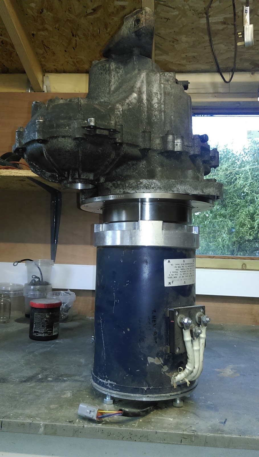
Finally got the motor connected to the gearbox and lifted it into the frame. I thought I would be pre-making the mounts but instead I offered the motor into place attached to the gearbox and hanging from a hoist, then using the gearbox mount bracket to set the position I measured and cut the other 2 mounts from an old scrap metal stand.
Curtis controller just tacked on to get the wires connected ready for a first run.
Here are some more photos of it in place
The lifting eye was balancing it quite well although the motor end was slightly heavier.
LH and front mount plates made from 3mm scrap sheet metal, it was already folded along some edges so I cut the shape I needed from it and didn't need to fold any parts
Offered the drive shafts up, had to unbolt the top of the shock absorbers to allow the arm to drop far enough to get the wheel end of the drive shafts in
Would of been almost impossible without the hoist as I could hardly lift the motor and gearbox together. Although new the hoist was surprisingly cheap from ebay.
Managed to find some time to get started on the motor mounting parts. A bit of a change of plan on ways to mount the motor to the gearbox, instead fo making a bespoke part from scratch I found that I could base the adapter on a standard disk brake as it was already the same shape. After looking around a bit I found a Suzuki Jimmy SUV front disk brake was the best fit, it has a 289mm OD and is 41mm deep, ideally it would have a 101.8 hole but it was 107 so I need to make a centering ring, but it's pretty close. I'm hoping the fact disk brakes are Iron/carbon is not going to be a problem, apart from being a bit heavy.
I've drilled it out to fit the gearbox, as I only have access to a mill without a readout the easiest way was to reference everything from a corner, this drawing shows the hole positions.
So I now have the mount plate made, and all the holes seem to line up quite well. Turned a couple of locators to help with final alignment onto the gearbox
Also turned the shaft to spline adapter, although I've simplified it a bit when I turned it as I wasn't able to do the rotated arcs on the manual mill, but the parts seem to fit together well.
So I've offered up the gearbox onto the motor with the parts and it looks ok, the thinner than originally planned disk based adapter does mean the end of the spline hits on the end of the motor shaft by 2mm but I'll cut off the end of the spline. Having the motor closer to the gearbox will be a big benefit to fitting the whole lot into the frame as there is very little space between the motor and frame.
Work on the conversion has been on hold for a couple of months now, with young children and work there's just not enough time left over to spend on this at all. Hopefully I can get back into doing some work on it again soon and finish off the mounts and drive connector. Once that's done then it's only a quick wiring up job to have it working on the stand.
Now everything is painted and cleaned it's ready to go together.
I don't yet have the motor mounting plate or shaft adapter but the frame can go together and I'll find out how much space there really is for the motor.
This is the lower arm assembly, just the hinging arm sitting on the coils.
I decided to make up a timber stand to hold the upper frame off the floor. This has made things a lot easier to work on. So now the gearbox is in place held by just one mount on the left hand side, the drive shafts aren't in properly yet as I've just remembered that I need to buy new oil seals so the drive shafts are just hanging in place for now. With the motor spaced as intended with the proposed mount plate it really does only just fit, this is purely a stroke of luck as it didn't occur to me that the motor was going to be longer than the original engine, fortunately the CAD model came out just about right which is useful to know.
So now I know it's all fitting I need to make up the motor-spline connection and wait for the motor mount to be machined. I've ordered the seals, didn't seem any point in ordering smart ones so I've ordered standard 40ID x 60OD x 10 wide R23 seals which are identical but only £3 each.
Now I can work out how to mount the motor to the two engine mount points, looking forward to wiring the motor now for the first test run.
One of the early things I checked on was is a 450 frame suitable to use for a roadster.. and it was apart from two things;
The handbrake cable points forwards to connect the the handbrake in the Roadster whereas it points up on a fortwo.
The Roadster doesn't use the anti-roll bar that normally comes with the fortwo frame.
So the anti-roll bar job was very easy and just involved cutting off the brackets..
The handbrake cable mod meant cutting off the old bracket and making a new one that points forwards, I knew what it should look like from my exiting Roadster so I managed to make a new bracket from the old bracket with a bit of cutting and folding and then welded it on. Susequently I have for the handbrake cables seem a bit short but if I don't clip it to the normal clip points then it works fine.
Having all the parts cleaned an painted seemed like a good opportunity to measure them up and model them in CAD. So now all the major parts are drawn and it looks like the motor is only just going to fit, it did come with a back plate to create a ventilation space and also protect the encoder on the back of the motor. However there is definitely no space for that so I've assumed it can't be fitted.
This view shows the motor and motor mount sectioned and the motor shaft mount and clutch spline.
I've bought a taperlock bush and flange plate to lock onto the motor shaft. The taper lock is a 1610 size with a 1 1/8" bore, the plate is a BF16 plate which is 120mm diameter with 6 x 8mm mounting holes at 110mm PCD.
Instead of buying a whole Smart clutch plate which normally comes as a complete assembly I've found that a Ford fiesta MK1 1.0 clutch plate fits the 19mm 17 spline shaft perfectly, just a few £s from ebay. So the plan is to cut off the clutch friction plate and use the inner plate and probably keep the springs as they will act as a bit of a shock absorber which might be useful.
I've had a go at controlling the gear selection motor and it seems to broadly work now. I've done a quick video to explain.
This is a better video with the voltage now running at 12v, motor takes around 5A on a move and has a bit of a kick to it.
I've had some requests for the Arduino code I used, this was based on some stuff I found on the web, (sorry but i can't remember the source) and my rather limited abilities with Arduino. I then connected this to Makerplot which is a serial port plotter capable of sending and reading some simple commands. It works in a rather odd way as the GUI is a macro you load up, but it's a great program once you're used to it.
So the Arduino code is shown below..
This is a link to the Makerplot software - http://www.makerplot.com/
and the is the macro for the Makerplot as shown on the vid.
This is the photo I found which shows the connection onto the Smart gear selection motor
also a handy schematic of the pins and encoders
----------------------------------- Code to drive motor as shown in the youtube video ------------------
please note, this is note code written spacifically for this project so there is some stuff in here which is not really needed... but it worked for me. You'll probably need to tweak around with the PID settings.
/*
This program uses an Arduino for a closed-loop control of a DC-motor.
Motor motion is detected by a quadrature encoder.
Two inputs named STEP and DIR allow changing the target position.
Serial port prints current position and target position every second.
Serial input can be used to feed a new location for the servo (no CR LF).
Pins used:
Digital inputs 2 & 8 are connected to the two encoder signals (AB).
Digital input 3 is the STEP input.
Analog input 0 is the DIR input.
Digital outputs 5 & 6 control the PWM outputs for the motor (I am using half L298 here).
Please note PID gains kp, ki, kd need to be tuned to each different setup.
*/
#include <SPI.h>
#include <PID_v1.h>
#define encoder0PinA 2 // PD2;
#define encoder0PinB 8 // PB0;
#define IS_1 0
#define IS_2 1
#define IN_1 3
#define IN_2 11
#define INH_1 12
#define INH_2 13
volatile long encoder0Pos = 0;
long previousMillis = 0; // will store last time LED was updated
long target1=0; // destination location at any moment
int countStep;
//for motor control ramps 1.4
bool newStep = false;
bool oldStep = false;
bool dir = false;
void loop(){
input = encoder0Pos;
setpoint=target1;
myPID.Compute();
pwmOut(output);
// print encoder and target every second throgh the serial port
if(millis() > previousMillis+200 ) {Serial.print(encoder0Pos); Serial.print(","); Serial.println(target1); previousMillis=millis(); //}
// interpret received data as an integer (no CR LR)
void doEncoderMotor0(){
if (((PIND&B0000100)>>2) == HIGH) { // found a low-to-high on channel A; if(digitalRead(encoderPinA)==HIGH){.... read PB0
if ((PINB&B0000001) == LOW) { // check channel B to see which way; if(digitalRead(encoderPinB)==LOW){.... read PB0
encoder0Pos-- ; // CCW
}
else {
encoder0Pos++ ; // CW
}
}
else // found a high-to-low on channel A
{
if ((PINB&B0000001) == LOW) { // check channel B to see which way; if(digitalRead(encoderPinB)==LOW){.... read PB0
// encoder is turning
encoder0Pos++ ; // CW
}
else {
encoder0Pos-- ; // CCW
}
}
}